OEM Coolant Compatibility, Wetted Materials, and Loop Cleanliness
Plain-English definition
The requirement that every metal, polymer, hose, and elastomer seal touched by coolant inside a Technology Cooling System (TCS) loop matches the exact fluid, inhibitor package, concentration, and temperature approved by the equipment manufacturer. Loop cleanliness combines fine filtration, pre-commissioning flushing, and scheduled lab checks to keep cold plates clean.
Why it matters on shift
Direct-to-chip cold plates route fluid through tiny microchannels (often 50 to 200 micrometers wide) that foul easily from construction grit, biological growth, or oxide flakes. Mixing unapproved metals or incompatible fluids can cause galvanic corrosion, inhibitor dropout, or seal damage over energized racks.
Illustrative operational example
In an illustrative liquid-to-liquid Coolant Distribution Unit (CDU) readiness check aligned with Open Compute Project (OCP) and ASHRAE liquid-cooling guidance, the isolated TCS loop uses an OEM-approved 25% inhibited propylene-glycol (PG25) fluid matched to a copper-and-stainless wetted-materials list. Crews flush through 25 micrometer duplex strainers before connecting racks and record baseline pH, inhibitor reserve, conductivity, and visual clarity.
Scope, code & safety boundary
Never top off a TCS loop with tap water, uninhibited deionized water, automotive antifreeze, or a mixed inhibitor brand without written OEM approval. Seal compatibility (for example, ethylene propylene diene monomer, EPDM, in water-glycol loops versus fluoroelastomer, FKM, in hydrocarbon or synthetic oil service) depends on exact compound, fluid and inhibitor chemistry, concentration, temperature, and OEM qualification rather than broad polymer rules. Dedicated Level 1 to Level 3 pre-functional flush and cleanliness commissioning scripts belong to the planned Prove Before Load candidate course (not published).

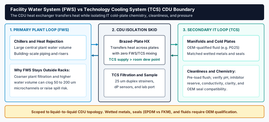
In a liquid-to-liquid Coolant Distribution Unit (CDU) topology, the brazed-plate heat exchanger transfers heat while isolating rack cold plates from central plant water volume, paired with 25 micrometer filtration and OEM-qualified wetted materials.
Read plain-text walkthrough of this diagram
Three-zone liquid cooling boundary diagram. Zone 1 (Primary Plant Loop, FWS) shows central chillers and large-volume building piping kept outside IT cold plates because coarser filtration can clog 50 to 200 micrometer microchannels. Zone 2 (CDU Isolation Skid) shows a brazed-plate heat exchanger transferring heat without mixing fluids, holding TCS supply above room dew point, and filtering through 25 micrometer duplex strainers with differential pressure sensors and a lab sample port. Zone 3 (Secondary IT Loop, TCS) shows rack manifolds and cold plates using OEM-qualified coolant (such as PG25), matched wetted metals and seals (EPDM vs FKM per exact OEM qualification), pre-load flushing, and scheduled chemistry checks.
Related courses & interactive lab practice
High-density AI cooling & commissioning
Maintenance procedures, hold gates & response
Practice live readings and switching in "120 kW GPU Direct-to-Chip CDU & Strainer Lab" with no login required.
Primary standards & technical references