Redundancy Topologies (N, N+1, and 2N)
Plain-English definition
Architectural capacity models where N is the minimum equipment needed to serve full design IT load, N+1 adds one independent spare module sharing that duty, and 2N duplicates two completely independent A and B paths end to end.
Why it matters on shift
Redundancy exists so single component failures and planned maintenance do not drop customer compute, yet operators inadvertently erase 2N fault tolerance whenever combined A-plus-B loading exceeds one surviving lineup's 100% continuous rating.
Illustrative operational example
Consider an illustrative symmetric 2N pair of 1,000 kW UPS lineups: carrying 430 kW on Bus A and 440 kW on Bus B (870 kW combined) survives a full Path B loss, whereas 580 kW per side (1,160 kW combined) overloads the survivor.
Scope, code & safety boundary
Illustrative <45% to 50% per-side 2N normal loading is a failover design implication, not a universal statute; always verify per-phase breaker ratings and site reserve ceilings.
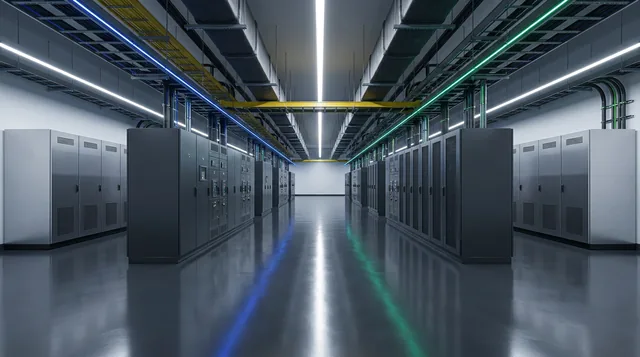
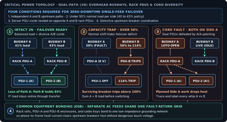
Dual-corded servers survive a single-feed outage only when Path A and Path B stay independent, each side runs below 50% normal load, power cords land on opposite PDUs, and breakers clear faults selectively over one common equipment ground.
Read plain-text walkthrough of this diagram
Panel 1 shows Busway A at 41% and Busway B at 43% feeding Rack PDU-A and Rack PDU-B, with Server PSU-1 on A and PSU-2 on B; losing Path A places 84% on Path B without tripping. Panel 2 shows Busway A at 58% and Busway B at 56%, where losing Path A pushes Path B to 114% and trips the surviving breaker. Panel 3 shows both PSU-1 and PSU-2 mistakenly plugged into PDU-A, dropping the host during planned Side A LOTO work. Callout 4 shows Rack rails and both PDU enclosures bonded to one common Equipment Grounding Bar.
Related courses & interactive lab practice
Facility, rack & safety foundations
Critical power & dual-path feeds
Air, chilled-water & liquid cooling
Maintenance procedures, hold gates & response
Shift command, permits & reliability
Practice live readings and switching in "NOC, Spine-Fiber & White-Space Walkdown" with no login required.
Primary standards & technical references